The History of Diaphragm Wall Panel Joints
In the early days of diaphragm wall construction the individual panels were dug with grabs with rounded clams so steel pipes, the same diameter as the thickness of the wall, were placed at the ends of the panels and extracted after concreting leaving a round hole filled with slurry. The hole helped guide the grab digging the adjacent panel and the system provided a semi-circular concrete construction joint between adjacent panels. There was no water bar.
As diaphragm walls became thicker and deeper so the steel pipes became bigger, longer and heavier requiring jointing systems to connect individual sections and jacking equipment to extract the pipe from the ground. As the depth of diaphragm walls increased so timing of this extraction process became more critical. Too soon and the unset concrete collapsed into the void, too late and the pipe became stuck fast into the hardening concrete. Great skill and experience was required to manage the process and diaphragm wall projects routinely worked late into the night.
As the use of diaphragm walls became more widespread, alternative shapes of joint formers came into use. The round ended digging grabs gave way to the more efficient square ended variety. The Italian company ICOS, the originators of the diaphragm wall method and probably the leading specialist diaphragm wall contractor in the world from the 1950s until the 1970s, started using a joint former which was shaped like a rectangle with an equilateral triangle on the concrete face. In the United Kingdom, “Organ Pipe” joint formers were used by Cementation. Both of these shapes were easier to extract than the earlier circular formers.
In the USA permanent end stops made up of large “I” beams with a void former on the soil side of the beam, which was removed during excavation of the adjacent panel, became the standard system. However most if not all examples of these types of walls were used for temporary soil support/water cut off and not as permanent structures. The beams were also used, sometimes with additional beams and/or bar reinforcement cages, to provide the tension element of the reinforced concrete. It seems likely that the adoption of this system had much to do with the high cost of labour making both steel fixing more expensive than in Europe and more particularly the overtime cost to extract joint formers would have been prohibitive especially in the major cities with powerful unions.
Towards the end of the 1980s and into the early 1990s two developments changed how diaphragm wall panel joints were formed. Both developments came from the French company now known as Soletanche Bachy.
One of the developments was the “Hydrofraise” now more commonly known as a “hydro-mill” or cutter. The cutting/milling wheels on this machine can cut into concrete but only if there is equal resistance to the machine’s excavation progress. If the machine is cutting equally into the concrete at each end of two separated panels then straight construction joints between the newly excavated panel and the already concreted panels on each side can be formed. A water bar cannot be included in the joint and with the possible exception of the Casagrande mill the method does not provide a significant shear key. The degree of panel to panel contact is determined by the excavation verticality that can be achieved. This joint system is now predominantly used in deep circular shafts where the walls are working in hoop stress so the joints are in compression making water leaks less likely and making shear keys unnecessary. Hydro-mills have great difficulty cutting into concrete at only one end of a trench. The differing resistance to excavation progress at one end of the trench, compared to the other end, would be difficult to manage and probably lead to unacceptable deviations in the verticality of the excavation.
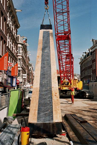
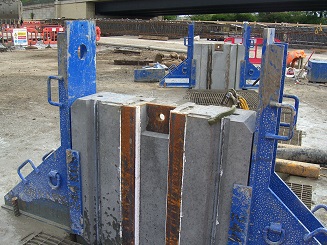
The other development was the system known as CWS or continuous water stop joints. In this system a steel plate with a steel trapezoid shape on one face is supported from the guide wall with the flat side against the soil at the ends of the panel excavation. In the middle of the trapezoid a fabricated clamp arrangement holds half of a rubber water bar. The protruding half of the water bar is then cast into the concrete. The joint former is later peeled away from the concrete during and after excavation of the adjacent panel leaving a shear key formed by the trapezoid shape with half the dumbbell water protruding out ready to be cast into the concrete of this next panel. This system had several major advantages over the earlier extraction systems:

- No late working and overtime to extract the joint.
- Better water tightness because of the rubber water bar that can now be introduced into the joint.
- Better panel to panel connection. Not always the case with the extraction systems where grab operator experience and competence was also a major factor.
- Simpler to use and less risk therefore requiring less experienced and less skilled personnel.
The CWS system was initially tried on relatively shallow 20m to 25m deep diaphragm walls. By the mid 90’s wall depths of 30m to 40m were using the system although now problems started to arise. Sometimes the former was difficult to peel off taking hours and in some cases days. A few formers broke with portions left behind in the joint. It became clear that if the former was slightly buckled or distorted in any way, or if it was not correctly positioned and suspended, or if the excavation was out of position/verticality then the grabs and/or chisels used to remove it started jamming in the excavated panel reducing their effectiveness.

The situation was probably worsened by the switch from rope grabs to hydraulic grabs that has been going on over the last twenty years. While there is no doubt that the modern steerable hydraulic grab digs deeper, faster and more accurately than the old rope grabs - the weight, lack of free fall capability, hydraulic connections etc. do not allow the equipment to be used as an effective chiselling tool which is really what is required to peel off a CWS former.
With special precautions the system has been used to depths in excess of 50m but the skill and experience required to do this is not easily found and even if possessed cannot always be present. Major difficulty or failure to remove the former can have major cost and programme implications for a project.
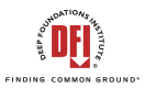
On some projects, where the diaphragm wall has been over 35m deep and the panels have either been excavated with grabs or with hydro-mills but without overcut joints, precast concrete “stop ends” have been used. This does reduce risk but at some cost penalty - partly from the manufacture and transport of the precast concrete sections and partly because their weight may require additional or larger cranes on site to lift and place the units.
Technically, it is probably fair to assert that they are a retrograde step, partly because double the number of joints in any wall increases the risk of leakage and partly because the nature of the stop end construction (especially shape) does not lend itself to an effective joint profile orincorporation of water bars further compromising water tightness. There is also greater potential for misaligned panel connections because of the difficulty of incorporating an effective grab guide in the relatively thin precast concrete section.
Hence the CCMJ Milled Joint!

European Patent 2732101 validated in: France, Germany, Italy & UK
US Patent 9371623. Other patents pending.
CCMJ Systems is a Corporate Member of the DFI